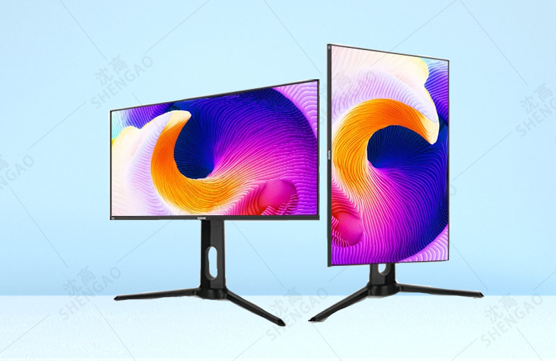
Generally speaking, the LCD consists of the following parts:
1. Liquid crystal module
Glass substrate: Inside are liquid crystals and gridded printed circuits. Timing control: Used to generate the timing and voltage required to control the deflection of the liquid crystal molecules. Light tube: produces a white light source. Backlight: Reflect the light produced by the lamp tube onto the LCD screen.
2. Control panel
The control panel acts as a signal converter. To convert various input format signals into fixed output format signals. For example, the input signal of 1024x768 screen can be 640×480, 800×600, 1024×768, etc., which can be converted into the output format of 1024×768.
3. Inverter
Generates high pressure for lighting the lamp tube.
Video amplifier circuit: it can be divided into two parts: previewing amplifier and viewing output. The preview amplifier is sent from the receiving display card in the signal interface. R, G, B three primary color video signal, to amplify it, so as to drive the output stage of the video amplifier. The output stage of the video amplifier is the power amplifier: large stage, the video signal sent by the pre-viewing amplifier stage is amplified to enough power, driving the cathode of the picture tube, modulating the strength of the cathode emission electron beam, electron beam bombardment of the fluorescent screen, it has completed the function of electro - optical conversion, and can display images with scanning.
Usually this part of the circuit also has contrast control, line field blanking, white balance adjustment and other functions.
Field scan circuit: including field oscillation and field output two parts. Under the synchronous signal of the field oscillation circuit, the field frequency sawtooth wave is formed, and the sawtooth wave is amplified by the power of the field output circuit and added to the field deflection coil to form the scanning current, so that the electrons emitted by the electron gun can be pulled up and down.
The field amplitude and field center adjustment functions are also realized in the field scanning circuit. In addition, the field frequency sawtooth wave is output to the pillow correction circuit to correct the horizontal pillow distortion.
Line scanning circuit: including line oscillation, line output, high voltage circuit, pillow calibration circuit and other parts.
Under the action of the line synchronization signal, the line oscillating circuit outputs periodic rectangular pulses, which drive the line output circuit to generate scanning current in the line deflecting coil.
The high-voltage circuit changes the voltage of the backsweep pulse with high amplitude generated during the reverse course of line scan, and then rectifies and filters to obtain the multi-channel voltage output, in which G1 is the gate voltage of the picture tube, Screen is the acceleration stage voltage, and Focus is the focusing pole voltage. H.V is the anode high voltage.
The realization of line center and line width adjustment is also included in the line scanning circuit.
Switching power supply: most displays use pulse-width modulated switching power supply, which consists of switching tube (adjusting tube), converter, sampling circuit, comparison amplifier circuit, reference power supply, driver and protection circuit. Switching power supply circuit is simple, easy to maintain.
Pattern recognition and control circuit: Line from the function of the circuit is based on the display card, a synchronous signal characteristics of judging the current which is a kind of display mode, and accordingly to control line scan and field scanning circuit, to eliminate the effects on the circuit working condition mode conversion, such as changing line oscillation, a free vibration frequency of the oscillation circuit, adjusting the line picture, field, change the line of the output stage working voltage, etc.


